You are here because you need reliable conductivity. That sounds obvious, but look around the industry: electrical failure starts, more often than not, at a poorly terminated connection. A weak crimp introduces resistance, generates heat, and eventually creates catastrophic downtime. This isn't theory. This is the field.
We aren’t aiming for "good enough" today. We are aiming for permanence. Installing pre-insulated terminals is a procedure requiring precision, not speed. Treat the process with the respect it demands, or expect to chase intermittent faults for the life of the installation.
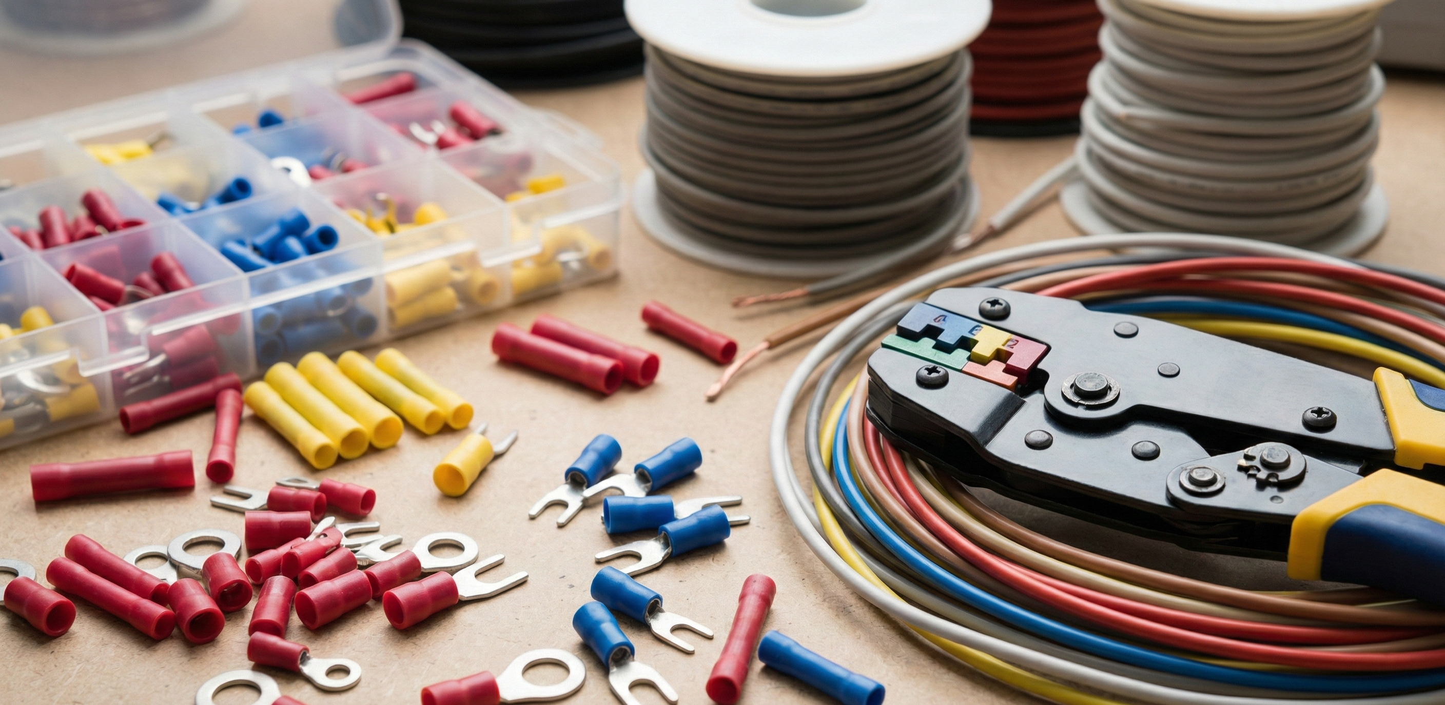
Tooling is Non-Negotiable. Choose the Right Crimp
The single most significant variable in terminal reliability is the quality of the crimping tool. Forget the stamped, multi-purpose pliers you found in the bottom of your toolbox. They are mechanical compromises designed for light duty, and they will fail you when dealing with sustained amperage loads.
You need a dedicated ratcheting tool.
A quality ratcheting crimper ensures a full compression cycle every single time, regardless of operator fatigue. It locks until the handles meet, guaranteeing the mechanical cold-weld between the conductor and the terminal barrel is optimized. Consistency drives reliability.
Understanding the Color Code
Pre-insulated terminals are universally coded to match specific American Wire Gauge (AWG) ranges. Use the correct die color for the wire you are working with. This is not optional.
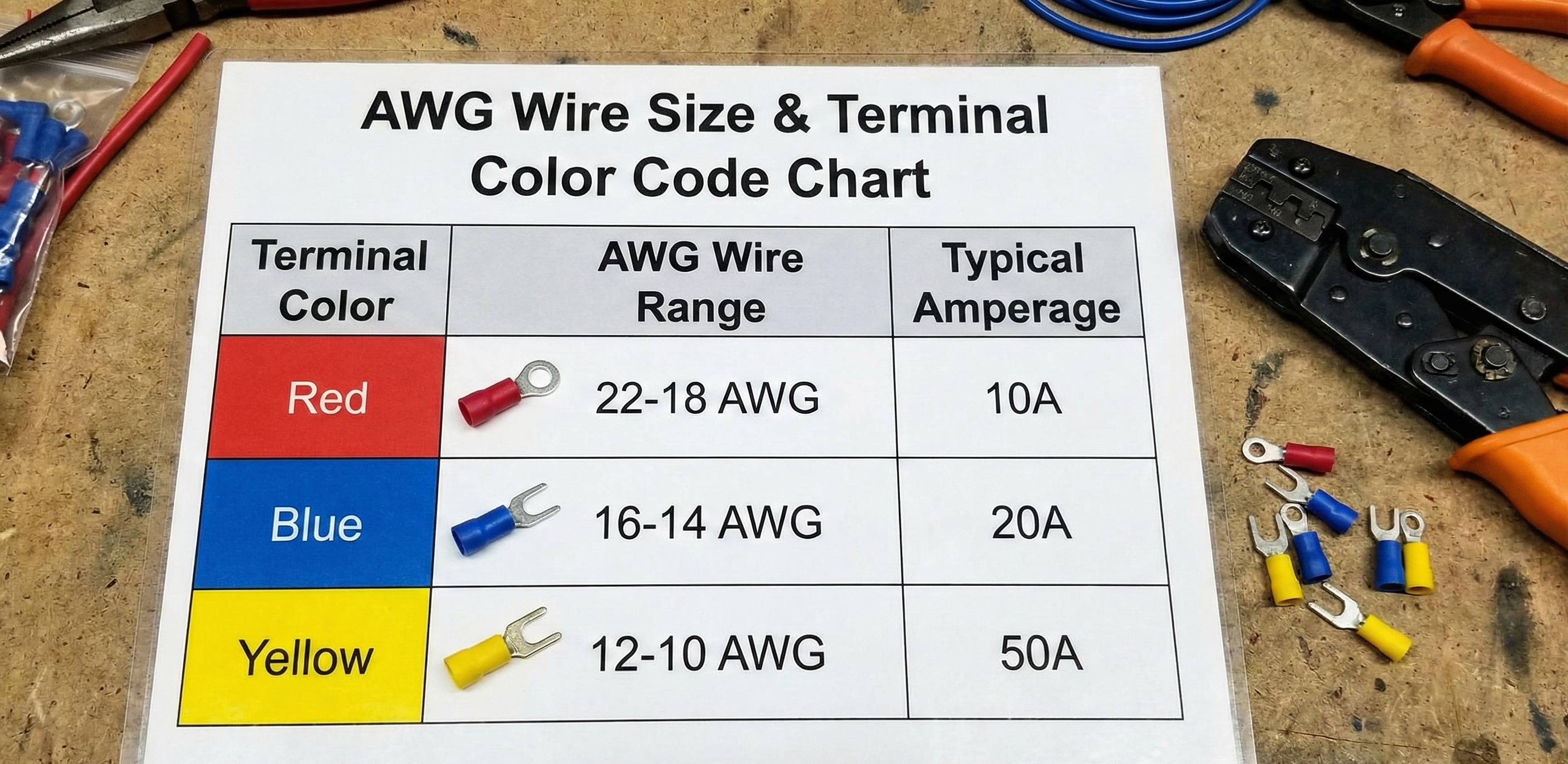
| Terminal Color | AWG Range | Typical Amperage |
|---|---|---|
| Red | 22 AWG to 18 AWG | Low current (up to 10A) |
| Blue | 16 AWG to 14 AWG | Medium current (up to 20A) |
| Yellow | 12 AWG to 10 AWG | High current (up to 50A) |
Attempting to crimp a 10 AWG yellow terminal using a red die will result in a fractured terminal body and insulation damage. Attempting to crimp an 18 AWG wire in a yellow die results in an under-crimped connection that will vibrate loose or generate excess resistance. Use the correct die. Every time.
The Prep: Strip Length and Wire Management
The integrity of the crimp begins long before the terminal touches the tool. It starts with the strip.
Precision matters here.
- Determine Strip Length: Use the terminal itself as your guide. The stripped conductor must be just long enough to reach the stop inside the metal barrel of the terminal, but not long enough to extend past the metal, where it could fray or contact other elements.
- Clean Cut: Ensure your wire strippers are sharp and the cut is clean. Nicked strands reduce the wire’s current carrying capacity and introduce stress risers. If you nick the strands, cut and re-strip.
- Twist the Conductor: Gently twist the exposed copper strands together. This helps gather all the conductors into a single unit, ensuring the entire bundle enters the terminal barrel uniformly.
How to Install Pre Insulated Terminals: The Five Steps
This process must be executed sequentially. Skip a step, compromise the connection.
1. Position the Conductor
Insert the prepared wire into the terminal barrel until the insulation butts firmly against the entrance of the insulation sleeve. You should see the bare copper pressed against the internal metal stop. If copper is visible past the plastic insulation collar, your wire is stripped too long; trim it.
2. Align the Terminal
Select the correct color-coded nest (die) on your ratcheting crimper. Place the metal barrel of the pre-insulated terminal into the nest. Crucial detail: terminals are formed from rolled metal and have a seam. Position this seam facing upward, opposite the indenting die of the tool. This ensures the maximum compression force is applied across the solid, strongest part of the terminal body.
3. Execute the Crimp
Actuate the tool slowly until the ratchet mechanism engages. Squeeze the handles firmly until the cycle fully completes and the tool releases automatically. The ratcheting action guarantees that the required compressive force is applied—you cannot cheat this step.
4. The Insulation Crimp
Modern, quality ratcheting tools often perform a dual crimp: one on the conductor and a lighter, secondary crimp on the insulation sleeve. This secondary action provides strain relief, ensuring vibration does not transfer directly to the conductor crimp. Check that the insulation sleeve has securely gripped the wire jacket without slicing or excessively flaring the plastic.
5. Verify and Test
Visually inspect the crimp. Ensure no strands are poking out the back and the insulation is not pierced.
Quality Control: If It Doesn't Pass the Pull Test, Start Over
The pull test is the definitive confirmation of your work. It is non-destructive verification that the cold-weld is structurally sound.
Immediately after crimping, apply a firm, steady pull on the wire, directly in line with the terminal body. You are testing the mechanical strength of the bond.
- A good crimp will feel absolutely rigid. The conductor should not move, slip, or stretch out of the terminal barrel.
- A failed crimp will feel spongy, or the wire will slide out entirely.
If the wire pulls out—even marginally—do not reuse the terminal. Cut it off, examine why the crimp failed (wrong die size, stripped too short, inadequate compression), and start the process again with a fresh terminal.
Your goal is zero movement. If the connection cannot resist manual force now, it stands no chance against the constant vibration and thermal cycling common in industrial environments. A connection you can trust is a connection that lasts the life of the machine. Build it right the first time.