Cable cleats are engineered components, specifically designed to withstand and manage the immense kinetic forces generated during a short circuit event. Failure to install them precisely, adhering strictly to manufacturer specifications and relevant standards, converts a safety system into a catastrophic liability.
If your installation crew treats cleating as a simple tightening task, you are fundamentally misunderstanding the physics involved. We are not just securing cables; we are locking down conductors that may experience outward forces equivalent to several tons per linear meter. This guide cuts the fluff. We focus on the necessary steps to achieve true IEC 61914 compliance and, more importantly, operational safety.
Preparation is Not Optional: Verifying the System Design
Before the first cleat is mounted, three non-negotiable checks must occur. Ignoring this initial planning phase is the primary reason for post-installation failure. You must confirm that the selected hardware aligns perfectly with the validated system design calculations.
The Three Pillars of Pre-Installation Verification
- Fault Current Validation: The cleat’s required specification hinges entirely on the calculated short circuit fault current (Ipk). Confirm the installed cleat material (e.g., Nylon 6/6, Aluminum) and design load rating meet or exceed the peak mechanical force (Fm) determined by the consulting engineer.
- Conductor Sizing and Type: Cleats are sized for specific cable diameters. Do not rely on visual estimation. Use a caliper. Verify the conductor arrangement matches the cleat design.
- Hardware Grade: This is where most installations fail. The strength of the cleat is irrelevant if the mounting hardware shears. You must use high-tensile fasteners (Stainless Steel A4/316).
Installation Sequence: Torque and Spacing Define Success
The mechanical integrity of the entire cable run is dictated by two variables: the precise spacing between cleats and the application of correct torque on the fasteners.
Calculating the Cleat Spacing (Lp)
Standard spacing tables often provide a good starting point, but they are general assumptions. The actual required spacing, Lp, is a function of the system’s peak fault current, the cable size, and the support structure’s rigidity.
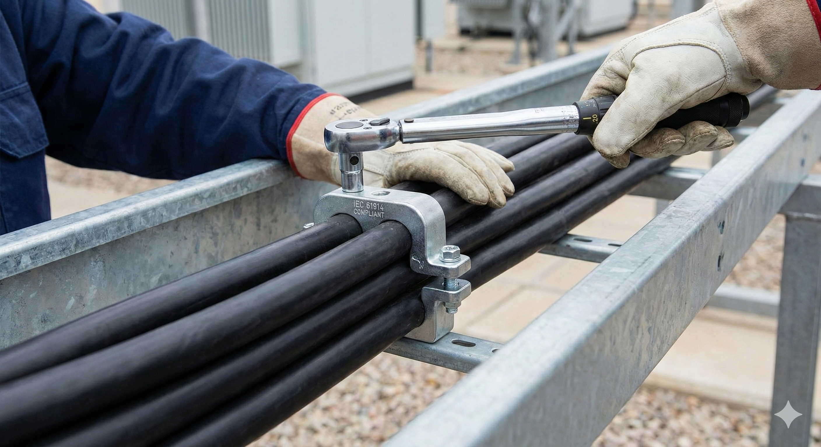
Securing the Cleat: Torque Is Everything
Warning
Do not guess the tension. Over-tightening crushes the cable insulation, leading to premature dielectric failure. Under-tightening allows movement during a fault.
The Common Pitfalls That Void Compliance
- Mixing Manufacturers: Never mix cleat models from different manufacturers.
- The Spacer Misuse: Ensure spacers are correctly oriented and secured before closing the cleat halves.
- Uncertified Supports: The cable cleat is only as strong as the support structure it is bolted to.
Cleating is a specialized mechanical task driven by electrical engineering requirements. By focusing on certified components, calculated spacing, and precise torque application, you move beyond merely strapping down cables and achieve robust short-circuit protection.